Friday, January 18, 2013

Breath and Note On/Off Transitions

If we're going to build a MIDI wind instrument controller, it's going to need to send MIDI note on and off messages - it's just part of the MIDI spec. But the tricky part is knowing when your breath is producing enough pressure to justify sending the MIDI note on message.

An approach that makes sense for our project is to choose some value a little above the "idle" value that the pressure sensor reads (that is, when you're not blowing into it). My sensor produces values of about 65 when I'm not blowing into it, and a threshold value of 100 seems to work well. In the Arduino sketches in this post, you may need to change the threshold value to something appropriate for the way your air tubing is set up, as well as your playing style. To adjust that threshold, look for the line:

#define NOTE_ON_THRESHOLD 100

And experiment with different values until you find something that works. Don't forget to recompile and upload the sketch after you make changes.

One Note


The following sketch reads the pressure sensor and sends a MIDI Note On event for middle C (the C about in the middle of the piano keyboard) when it detects that the pressure is above the threshold value. It sends a MIDI Note Off event when the pressure is below the threshold value. It also keeps track of whether a note is sounding or not, so it knows if a Note On/Off message needs to be sent (if the note is already on, we don't need, or want, to send another Note On message).

#define MIDI_CHANNEL 1
// For this sketch, we only can play one note
#define MIDI_NOTE 60 // Middle C (C4)
// The threshold level for sending a note on event. If the
// sensor is producing a level above this, we are in note on
// state, otherwise note off
#define NOTE_ON_THRESHOLD 100

// We keep track of whether a note is sounding or not,
// so we know whether to send a note on or off event.
boolean noteSounding = false;
// The value read from the sensor
int sensorValue;

void setup() {
  // Nothing to initialize for this sketch
}

void loop() {
  // read the input on analog pin 0
  sensorValue = analogRead(A0);
  // Send the appropriate MIDI note on or off message
  if (sensorValue > NOTE_ON_THRESHOLD) {
    if (noteSounding) {
      // Nothing to do - note is already on
    } else {
      // Value has risen above threshold - turn the note on
      usbMIDI.sendNoteOn(MIDI_NOTE, 100, MIDI_CHANNEL);
      noteSounding = true;
    }
  } else {
    if (noteSounding) {
      // Value has fallen below threshold - turn the note off
      usbMIDI.sendNoteOff(MIDI_NOTE, 100, MIDI_CHANNEL);
      noteSounding = false;
    } else {
      // Nothing to do - note is already off
    }
  }
  // Delay a bit to avoid glitches (very short notes that
  // sound because the breath falls below the threshold
  // value, then goes back above it). Adding 20
  // milleseconds of delay reduces the responsiveness
  // of the instrument, and we'll discuss better ways
  // of handling this in later posts. For now, this is
  // good enough.
  delay(20);
}

Here's how the sketch sounds when playing the Grand Piano patch from GarageBand.

Four long notes:


A synth pad, long notes:


And to test the responsiveness, here I'm playing faster and faster notes (using a technique called double-tonguing and then flutter-tonguing). It keeps up pretty well:


Ok, great. We can send MIDI Note On/Off messages. But this is pretty boring, only playing one note. We'll be talking about how to select notes based on fingerings in later posts, but let's at least make our sketch choose a couple of different notes at random.

Here's a modification to the previous sketch. Instead of always sending a middle C for the note, whenever a Note On event is to be sent, it randomly chooses one of 5 notes from a pentatonic scale by using the random() method from the Arduino library. Look at the get_note() method - that's where we pick the random note to play. The Arduino library's random() method picks a number from 0 through 4 for us, and we use that to select one of the MIDI notes 60 (middle C), 62 (D), 65 (F), 67 (G), or 69 (A).

#define MIDI_CHANNEL 1
// The threshold level for sending a note on event. If the
// sensor is producing a level above this, we are in note on
// state, otherwise note off
#define NOTE_ON_THRESHOLD 80  

unsigned int notes[5] = {60, 62, 65, 67, 69};

// We keep track of which note is sounding. The value
// -1 means no note is sounding.
int noteSounding = -1;
// The value read from the sensor
int sensorValue;

void setup() {
  // Nothing to initialize for this sketch
}

int get_note() {
   return notes[random(0,4)];
}

void loop() {
  // read the input on analog pin 0
  sensorValue = analogRead(A0);
  // Send the appropriate MIDI note on or off message
  if (sensorValue > NOTE_ON_THRESHOLD) {
    if (noteSounding != -1) {
      // Nothing to do - note is already on
    } else {
      // Value has risen above threshold - turn the note on
      noteSounding = get_note();
      usbMIDI.sendNoteOn(noteSounding, 100, MIDI_CHANNEL);
    }
  } else {
    if (noteSounding != -1) {
      // Value has fallen below threshold - turn the note off
      usbMIDI.sendNoteOff(noteSounding, 100, MIDI_CHANNEL);
      noteSounding = -1;
    } else {
      // Nothing to do - note is already off
    }
  }
  // Delay a bit to avoid glitches (very short notes that
  // sound because the breath falls below the threshold
  // value, then goes back above it). Adding 20
  // milleseconds of delay reduces the responsiveness
  // of the instrument, and we'll discuss better ways
  // of handling this in later posts. For now, this is
  // good enough.
  delay(20);
}


Here's how it sounds. I'm playing a syncopated rhythm, using the GarageBand Grand Piano patch. Notice how the note pitches change randomly:

Here I'm playing the new sketch and using the "Kotu Chords" patch from GarageBand's Synth Textures collection, but playing the same rhythm. This patch harmonizes the input notes, so even though the get_note() method only produces one randomly selected note, once I feed that note into the synthesizer, I get about 4 notes out.


A cool aspect of this sketch is that, since we're using the random() method from the Arduino library to choose which note to play, two performances of the same piece on this instrument are likely to be very different. And by combining our pretty simple breath based controller with some interesting patches from GarageBand, we're able to make some interesting sounds. Try playing around with different patches in GarageBand, or if you're using a different audio environment and/or OS, experiment with what you have. Upload your creations and share links to them here.

Next

While these sketches can produce some interesting sounds, they are pretty much devoid of expression. All the notes are exactly the same volume, and we have no control over how the note evolves over time. In my next post, I'll talk about how to create an instrument that is much more responsive to the nuances of breath control.

Tuesday, January 15, 2013

Building a Breath Controller


In this project, I'll build on my previous post on reading breath pressure into an Arduino or Arduino clone. We'll use the same circuit from that post, and write some new code that maps the sensor values we read to a MIDI continuous controller (which I'll refer to as a CC from here on out). That CC data will, in turn, control a parameter of a software synthesizer.

What's a MIDI CC?


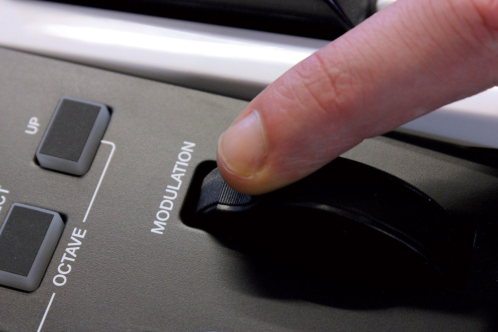
MIDI continuous controllers are a standard way for performers to modify the sound produced by the synthesizers they are playing. The "continuous" part of the name means that the values sent on the MIDI bus control some parameter with a range. If you've played a MIDI keyboard that has a modulation wheel:


you know that the more you turn the "mod wheel", the more vibrato you hear, at least with most common synth patches. In the following example, I play a chord, and turn the modulation wheel from zero to full on, then back to zero.

If you dig into the MIDI spec, you'll discover that the mod wheel is only one of many continuous controllers defined. Each one has a unique number assigned to it, and some have a name, like "Modulation Wheel" or "Pan". The controller name describes what type of control is typically going to generate that data. On a traditional MIDI keyboard, if you move the mod wheel, you'll generate Continuous Controller 1 data.

If you think about it, there are many real-life things that naturally can be expressed as a continuous controller: How far you have twisted a knob. How far to the left or right your are tilting your hand. How far apart your hands are. Or how hard you are blowing air. All of these things can be mapped to some number that ranges from some minimum value to some maximum value (provided you can measure them and translate them to MIDI).

The MIDI spec states that continuous controller values vary from a minimum value of zero to a maximum value of 127. This means CC values have 7 bit resolution, which, for some applications, is not acceptable - the results sound odd. I'll talk about those later, but for many of the common synthesizer parameters that are controller by CCs, 7 bits is fine.

How the Pressure Sensor Works


Before we get into wiring up and coding the project, let's dive into how the Freescale pressure sensor works. It relies on something called the Piezoresistive Effect.

There are some materials that exhibit the property that, as you press on them, the resistance through the material changes. The Freescale sensor has a small piece of this type of material inside, and when the pressure inside the case of the sensor increases, the resistance through this material changes. The sensor also has circuitry to amplify the signal and make it work consistently even if the temperature varies.

Advances in chip fabrication techniques have allowed manufacturers to make these type of sensors in very small packages. By contrast, the Yamaha WX-7, a 1980s-era wind instrument controller, has a breath sensor that is much larger than the Freescale sensor used in this project. Although I don't know how the WX-7's pressure sensor works, I suspect it's based on the same principle.

Mapping Sensor Values

We'll now build on the circuit in my previous post and generate MIDI continuous controller data based on how hard a performer is blowing into the breath sensor.

Remember that our Arduino's analog inputs convert the values they read into a value that varies between 0 and 1023. But the MIDI spec wants you to provide values between 0 and 127. What to do?

Well, the math is pretty simple. Just divide the value read from the input by 1024, and multiply it by 128. But the arduino library has a nice convenience function named map() that does exactly this. For example:

  int sensorValue1 = analogRead(A0);
  int ccVal = map(sensorValue1, 0, 1023, 0, 127);

The code snippet above will linearly map values in the range 0-1023 to values in the range 0-127.

Generating MIDI CC Values

The PJRC USB MIDI support makes sending MIDI data over USB just ridiculously simple. From the PJRC USB MIDI reference:

usbMIDI.sendControlChange(control, value, channel)

 Where "control" is the MIDI controller to change, "value" is the mapped sensor value, and "channel" is the MIDI channel on which to send the data. Although we haven't talked about MIDI channels yet, for these exercises we'll send the data on MIDI channel 1 and then make sure that our MIDI synthesizers are either set up to listen on channel 1 or are set to "omni" mode, in which they respond to MIDI data on any MIDI channel.

Our First, and Imperfect, Sketch

#define MOD_WHEEL_CONTROLLER 1
#define MIDI_CHANNEL 1

// The value read from the sensor
int sensorValue;
// The CC value we will send
int ccVal;

void setup() {
  // Nothing to initialize for this sketch
}

void loop() {
  // read the input on analog pin 0
  sensorValue = analogRead(A0);
  // Map the value, which may range from 0 to 1023,
  // to a value in the range 0 to 127, which is
  // the valid range for a MIDI continuous controller
  ccVal = map(sensorValue, 0, 1023, 0, 127);
  // And send the value as a MIDI CC message
  usbMIDI.sendControlChange(MOD_WHEEL_CONTROLLER, ccVal, MIDI_CHANNEL);
}


 To load this sketch, first go to the "Tools" menu and choose "USB Type" and select "MIDI". Then click on the upload button.

Once you've loaded the sketch, you'll need to load a software synthesizer host on your Mac/PC/Linux box. While I can't cover every possibility in this post, I'll cover the basic steps for running Garage Band on a Mac and getting mod wheel output from our circuit.

  1. Start Garage Band.
  2. If a project opens automatically, choose Close from the File menu and choose New Project...
  3. Select the Keyboard Collection template and give the project a name in the dialog that appears.
  4.  In the list of instruments that appears, click on "80's Sync Lead" - it's an interesting-sounding synth that responds to mod wheel input.
  5. Select Musical Typing from the Window menu. A window appears where you can click on a virtual MIDI keyboard.
  6. If your Teensy controller isn't plugged in, plug it in now. When you plug in a MIDI-USB device, GarageBand should pop up a window informing you that the number of MIDI inputs has changed.
  7. Click and hold down the mouse button on a note in the Musical Typing window. In the sound sample below, I clicked and held the "F" key.
  8. You should be hearing a synthesizer playing a note now. Keep holding the mouse button and blow into the tube connected to your pressure sensor. Start blowing gently, blow harder and harder, then gradually blow less and less.
  9. You should hear something about like this

And if you double-click the segment you just recorded, and select "Modulation" from the "View" menu, you can see a graph of the values the Teensy sent.

Pretty cool, huh? Actually, no, there are two serious problems with my sketch.

Shut Up, Already!

Notice that we send a MIDI CC value every time the the loop() method is called. This means that you're spamming the MIDI instruments as fast as your microcontroller can make it through its loop() method. This is not good because (a) the MIDI bus has a finite bandwidth, and (b) you can overload software synthesizers with this data, as they try to adjust internal parameters in real time.

There are two approaches I can think of to address this problem:
  1. Only send a new CC value if a certain amount of time has passed, e.g. 20 milliseconds, or
  2. Only send a new CC value if the new value is different from the previously sent value to be interesting to the synthesizer.
The first method is really easy to implement.  Here's a sketch that will only send CC values every 20 milliseconds.

#define MOD_WHEEL_CONTROLLER 1
#define MIDI_CHANNEL 1
// Send continuous controller message no more than
// every CC_INTERVAL milliseconds
#define CC_INTERVAL 20

// The last time we sent a CC value
unsigned long ccSendTime = 0L;
// The value read from the sensor
int sensorValue;
// The CC value we will send
int ccVal;

void setup() {
  // Nothing to initialize for this sketch
}

void loop() {
  // read the input on analog pin 0
  sensorValue = analogRead(A0);
  // Map the value, which may range from 0 to 1023,
  // to a value in the range 0 to 127, which is
  // the valid range for a MIDI continuous controller
  ccVal = map(sensorValue, 0, 1023, 0, 127);
  // And send the value as a MIDI CC message
  if (millis() - ccSendTime > CC_INTERVAL) {
      usbMIDI.sendControlChange(MOD_WHEEL_CONTROLLER, ccVal, MIDI_CHANNEL);
      ccSendTime = millis();
  }
}

Don't Send Useless Data

The other problem is that, even when you aren't blowing into the tube, it's sending data to the MIDI instruments. If no air is going through the tube, then why send any data at all?

This is pretty easy to fix. Recall that, even when no air was being blown through the tube, it produced a voltage that the analog-to-digital converter on the Arduino interpreted as about 64. So, if the value we read from the input port is less than about 70, let's just not send anything at all. Problem solved.

One subtle issue is that when the pressure falls below the threshold value, we need to  send a zero value. Otherwise, when you stop blowing, the controller would remain at the last value we sent, rather than zero. We handle this in the last else clause.

#define MOD_WHEEL_CONTROLLER 1
#define MIDI_CHANNEL 1
// Send continuous controller message no more than
// every CC_INTERVAL milliseconds
#define CC_INTERVAL 20
// Only send CC data if the pressure sensor reading
// a value larger than this.
#define BREATH_THRESHOLD 70

// The last time we sent a CC value
unsigned long ccSendTime = 0L;
// The value read from the sensor
int sensorValue;
// The CC value we will send
int ccVal;
// The last CC value we sent
int lastCcVal = 0;

void setup() {
  // Nothing to initialize for this sketch
}

void loop() {
  // Only read the sensor if enough time has passed
  if (millis() - ccSendTime > CC_INTERVAL) {
    // read the input on analog pin 0
    sensorValue = analogRead(A0);
    if (sensorValue > BREATH_THRESHOLD) {
      // Map the value, which may range from BREATH_THRESHOLD
      // to 1023, to a value in the range 0 to 127, which is
      // the valid range for a MIDI continuous controller
      ccVal = lastCcVal = map(sensorValue, BREATH_THRESHOLD, 1023, 0, 127);
      // And send the value as a MIDI CC message
      usbMIDI.sendControlChange(MOD_WHEEL_CONTROLLER, ccVal, MIDI_CHANNEL);
      ccSendTime = millis();
    } 
    else if (lastCcVal > 0) {
      // The pressure has just dropped below the threshold, so
      // send a CC value of zero
      usbMIDI.sendControlChange(MOD_WHEEL_CONTROLLER, 0, MIDI_CHANNEL);
      ccSendTime = millis();
      lastCcVal = 0;
    }
  }
}


Another thing you can do with this code is convert it to a MIDI Breath Controller and do cool stuff like in this video:


You can build that For about $36.

Next


In the next post, I'll show how to use the pressure sensor to manage MIDI Note On and Note Off events, which will allow us to articulate like a woodwind or brass player does.


Sunday, January 13, 2013

Breath Sensing 101

In this post, I'll discuss very basic breath sensing. We'll use a Freescale pressure sensor to detect how hard a player is blowing into a tube, and we'll print out the values being read. In later posts, I'll show how to convert those raw sensor values into MIDI continuous controller messages that we can use for expressive control of a MIDI synthesizer.

What you'll need:
  • A microcontroller. In my examples, I will use the Teensy 2.0 microcontroller from PJRC. You can use any Arduino-compatible microcontroller for these examples, but once we start using MIDI, it will be a lot easier if you have the Teensy, as it has MIDI-over-USB support built in. This means that you can plug the Teensy into your computer's USB port and directly drive a software synthesizer. I have a Mac so I'll use Garage Band for the demos, but, you can use any instrument "host" that allows you to run Apple or VST instruments. Hosts are available for Macs, PCs, and Linux.
    By the way, I recommend ordering the Teensy with pins pre-soldered, so that you can easily plug it into a breadboard while prototyping.
  • A USB cable for the microcontroller.
  • A Freescale MPXV4006GP (pdf spec sheet). You can order one from Mouser Electronics (direct link). They are about $13.00 in single quantities.
  • A suitable breadboard and jumper kit for connecting the components together. Maker Shed is a great place to get things like this, and also has a bundle of a breadboard and a jumper kit. For prototyping, I prefer flexible jumper wires, which Maker Shed also has.
  • Some heat-shrink tubing, which we'll use to make an initial attachment to the pressure sensor. I would recommend getting an assortment of heat shrink tubing sizes either online or at Radio Shack - you'll use it a lot if you do any serious amount of hacking.
  • Some 1/4" drip irrigation tubing - a few feet will do. This should be available at any hardware store or garden supply center. We'll slip this tubing over the heat shrink attached to the sensor, and the inside diameter of the irrigation tubing is close enough to the outside diameter of the heat shrink that it makes a decent seal, even without gluing it.
  • A few pushbutton switches for use in later projects where we'll be simulating woodwind keys and trumpet valves. I like the tactile button assortment available from SparkFun, but any momentary pushbutton switch that can plug directly into the breadboard will work. If you get a "Getting Started with Arduino" kit, available from a number of places, it will probably include something suitable.
  • Some solderless headers, which we'll use to attach legs to the Freescale sensor. Since the sensor is a surface mount device, it won't directly plug into the breadboard. However, its pins use the same spacing as the holes in the breadboard, so soldering 4 pins on each side of the sensor will allow us to plug it in.
  • Soldering iron, solder, and some basic soldering skills.
Preparing the Pressure Sensor

As I mentioned, the Freescale pressure sensor is a surface-mount device. Typically, a machine will place the part on a circuit board and use hot air to melt a solder paste that affixes the part directly to metallic pads on the board. This is cheaper to make/assemble than the older "through-hole" type of part, where legs on the part go through the circuit board and are soldered into the hole. It's getting harder and harder to find through-hole versions of components, so some companies like SparkFun provide "break-out" boards, which a small circuit board with the surface-mount component soldered to it, and standard-spaced holes which can be soldered to. For example, look at SparkFun's breakout board for the VS1033D MP3 chip. The chip has 50+ very tiny pins which would be extremely difficult to hand-solder (some people can do it - not me).

Fortunately, the Freescale sensor we're using is much simpler. In fact, even though there are 8 pins on the device, only three are used (in this drawing, the active pins are the three on the right side - pins 2, 3, and 4.


What I did was use a Helping Hands to hold the sensor and a set of  of the header pins against the sensor legs, after I flattened out the legs so they pointed straight down. I then soldered each of the 4 header pins to the sensor pin it was touching, and repeated it with the 4 pins on the other side. The result looks like this:


Try to work fast so you don't overheat the sensor electronics.

In that photo you can also see how I attached some heat-shrink tubing (the red tube) to the input port of the sensor, and then slipped some irrigation tubing over that (the black tubing). Use a lighter to heat the heat shrink tubing where it mates with the sensor's input tube so it makes a tight seal.

Now we're ready to hook things up on a breadboard (click to view a larger version):

This shows a Teensy 2.0, so if you're using some other microcontroller, hook up pin 4 of the sensor to Analog input zero.

A schematic of this circuit is:


Once that's all wired up, attach the USB cable to the controller and hook it up to your PC. Start the Arduino development environment (if you're using a Teensy, you'll also want to install PJRC's Teensyduino add-on which makes it possible to use the Teensy just like any other Arduino device from within the dev enviroment. Here is a simple sketch that will just print out the values being read from the sensor:
// the setup routine runs once when you press reset:
void setup() {
  // initialize serial communication at 9600 bits per second:
  Serial.begin(9600);
}

// the loop routine runs over and over again forever:
void loop() {
  // read the input on analog pin 0
  int sensorValue1 = analogRead(A0);
  Serial.print(sensorValue1);
  Serial.println();
  delay(100);        // delay 100 milliseconds (1/10 of a second)
}

If using a Teensy, make sure the "USB Type" option in the "Tools" menu is set to "Serial". Choose the correct board type and serial port from the Tools menu, then upload the sketch to the board.

To see the values being read, choose "Serial Monitor" from the "Tools" menu and set the baud rate to 9600. You should see a series of values being printed. Without blowing the tube, I see values of about 64, which probably corresponds to ambient air pressure. Blowing into the tube, you should be able to max out the sensor, meaning it will produce a reading of close to 1023 (the maximum value that the 10-bit analog-to-digital converter on the Arduino will produce).

In the next post, I'll describe how to map these raw values to MIDI continuous controller data, and how to use that to control MIDI synthesizers.

A Series: Basics of DIY Wind Controllers

Over the past few years I've spent some time thinking about and designing wind instrument controllers. I thought a good way to give something back would be to produce a series of blog posts describing what I've learned while tinkering with my projects.

As it turns out, I'm not a very skilled craftsman, so most of my projects end up looking like something Homer Simpson would have created. But I think I've learned a few things about building the electronics and writing code. So, in this series of posts, I'm going to concentrate on sharing some basic building blocks and core concepts, like the following:
  • Why electronic wind instruments are hard
  • Breath Sensing 101
  • Mapping analog readings to MIDI continuous controller values
  • MIDI note selection methods
  • Using sensors to alter performance data in real time
  • And more, as I think of them

Since I've been using Arduino and Teensy microcontrollers to do my experiments, I'm going to focus on those, so the code examples will target those platforms.

If you are a performer who uses an EWI, EVI, or WX-series controller, there won't be a lot of practical advice for you here, but the circuits and code may help you understand what's going on inside your instrument. Also, the posts on building synth patches that work well with wind controllers will certainly be applicable to your live rigs. So, please - read on!

So, onto post number one:

Why Electronic Wind Instruments are Hard

First of all, if you're not familiar with what an electronic wind instrument is, I'll define the term.

An electronic wind instrument is a musical instrument that employs electronics to produce the instrument's sound, and is articulated by blowing into the instrument.

There are a number of commercially available electronic wind instruments. The most common instruments are the EWI series from Akai, and the WX-5 from Yamaha. Both are woodwind-style controllers - that is, they are fingered in a way that is easily learned by someone who knows how to play the saxophone, clarinet, or flute. The Akai instruments also support a mode that is more natural for trumpet players to use.

The Akai instruments are the latest in a long line of wind controllers that started with Nyle Steiner's work in the 1970s. For more information on this history of the Steinerphone/EWI, see the Nyle Steiner home page. For more links to learn about wind controllers, check out the Wind Controller links page from Patchman Music. These two paragraphs don't come close to describing the history of wind controllers, but the links page on the Patchman site is an excellent resource to learn more.

(Aside: Nyle Steiner also invents lots of other crazy stuff. And he's a ham like me.)

ADSR


The majority of electronic instruments you can buy are really good at emulating instruments that can be modeled with the ADSR model (Attack, Decay, Sustain, Release):


This model describes how a sound evolves over time. For example, when you hit a key on a piano, there is an initial attack A, when the piano's hammer hits the string. After the initial strike of the hammer (the attack phase of ADSR), the string starts vibrating, and the vibration starts to lose energy. In most cases, the majority of the string's vibrational energy dissipates quickly (the D - decay phase), but then the string continues to vibrate at a lower volume, fading out gradually (the S - sustain phase). When the key is released, the piano's felt damper touches the string, stopping the vibrations (the R - release phase). Most synthesizer patches have a fixed ADSR envelope, a "recipe" for the sound as it progresses through time. For a plucked or struck instrument, the performer has some control over the duration of these phases, and can also exert some control over the initial input, e.g. how hard the string is plucked or how hard the drum head is struck.

ADSR works really well for modeling instruments that are plucked or struck, which includes most of the staple instruments of popular music like:
  • Guitar
  • Bass
  • Drums
  • Piano and other keyboards
Wind instruments, on the other hand, don't follow this model at all. The sound is produced by a column of air emanating from the performer's lungs, which in turn causes something to vibrate - a single reed (clarinet/saxophone), two reeds (oboe/bassoon), lips (trumpet/horn/trombone/tuba), or the air column itself (flute/recorder). Articulation (the starting and stopping of sound) is generally accomplished by interrupting the stream of air using the tongue. The ADSR model simply doesn't reflect the way wind instruments work. It also doesn't model the way that bowed instruments like the violin make sound either.

Due to the popularity of the instruments that ADSR models well, manufacturers of electronic musical instruments have generally not found other types of instruments to be commercially viable. Yamaha and Akai have a series of wind controllers that emulate woodwind instruments, and some smaller companies produce small quantities of instruments that emulate other types of instruments, including trumpets and violins, but for the most part, wind players have not been invited to the electronic music party until they learn to play a different instrument.

For this reason, even if you have a wind instrument controller like one from Yamaha or Akai, you're faced with the difficult task of finding synthesizer patches that work well with your controller. If you *want* to sound like a Fender Rhodes electric piano, no problem, but if you want to make that Rhodes fade in from nothing, swell up, and fade out, sorry, you're out of luck. The ADSR envelope of the Rhodes patch you have models the characteristics of the real Fender instrument.

I'll cover this topic in more detail in a later post, but the important thing to remember is that if you want to play your wind instrument controller in an idiomatic way, you're going to have to either go find some patches specifically designed for wind controllers, or build your own.

I should also mention that my work has focused on building instruments that send MIDI data, but an equally valid approach is to build instruments that send raw sensor data to a device that makes the sound itself, rather than relying on a MIDI synthesizer to make the sound. The original Steiner EWI and Akai variants had a dedicated synthesizer that directly read the instrument's sensors. Another option is to feed all the sensor outputs to a computer. The computer, in turn, uses a sound system like pd or Max to realize the sound. There are a number of artists using that approach, but one of the most exciting, in my opinion, is Onyx Ashanti, who is really pushing the envelope on the form factor for wind controllers. He started with a Yamaha wind controller, deconstructed the functionality it provided, scratched some personal itches he had with performing live, and arrived at the Beatjazz Controller. I encourage you to follow his work.

What's Next


In the next post, I'll select an inexpensive sensor that you can use to sense breath pressure in a wind controller. We'll cover how to connect it to an Arduino or Teensy controller, and how to connect tubes to the sensor so you can blow into it and measure the breath intensity.

Wednesday, July 4, 2012

After a long hiatus, I'm back!

(In which I give a big shout-out to PJRC, designers of the Teensy)

I got inspired to do more work on my Gordophone project when I saw that the Teensy 2.0 had native support for USB MIDI. If you're unfamiliar with Teensy, it's a dynamite little ATMega-based microcontroller that is extremely compatible with Arduino, but also allows you to turn it into a USB device.

I've always been bummed out that, in order for my instruments to drive software synthesizers on my Mac, my designs needed a MIDI shield bolted to the Arduino, and a MIDI interface connected to the Mac, using those 1980s DIN-5 connectors - very unwieldy.

There is a standard for transporting MIDI messages over USB, and any modern music device you get these days will allow you to attach it to your computer via USB. So if, say, you go to your local music store and buy a keyboard, it'll have a USB connector. Plug it into your Mac, start up Garage Band, and you can control the softsynths.

Since Teensy 2.0 has USB-MIDI support built in, this means that the Gordophone can shed all those MIDI cables and interfaces, and work directly over the USB cable that connects the Teensy to the computer.

Also, Teensy is, well, teensy. It's barely bigger than a U.S. Quarter, yet has all the I/O I need to build the Gordophone, and if I need more I/O pins, I can use the Teensy 2.0 ++ (the big brother to the Teensy, which, while being a larger sibling, is still pretty damn small). I'm hoping to be able to embed the controller directly into the instrument in future designs.

PJRC is the company that sells the Teensy. I placed an order with them via the web, received a prompt acknowledgement of my order, and received my order a couple of days later (I'm on the US west coast, so shipping time from Oregon is fast). The Teensy is well-supported with plenty of downloadable sample code.

My first milestone was to put together a simple instrument - a single button that sends a random MIDI node on event when pressed, and sends a note off event when the button is released. Following the help files on the PJRC website, I had my simple instrument running in less than 30 minutes, and the code worked the first time (that *never* happens at my day gig).

My next milestone was to port my old Arduino-based Gordophone sketch to the Teensy.

First, I had to solder up an adapter that would plug into the DB-25 connector on the Gordophone and bring out the individual wires so I could plug them into a breadboard and wire them up to the Teensy:


And then it was a matter of digging up my project docs to remember which of the Gordophone sensors were connected to which input pins on the Arduino. The pins on the Teensy are different, but PJRC thoughtfully provides a reference card that maps the Arduino pin numbers to the Teensy pin numbers. Looking at that, I was able to patch the DB-25 to the Teensy:


Also, I should mention, PJRC has done a fabulous job of integrating the Teensy into the Arduino IDE, via the Teensyduino package. Apart from requiring that you press the Teensy's reset button once, the developer experience is exactly the same as using an Arduino.

Since I have been inactive for a while, getting things running on the Teensy also required porting some code to Arduino 1.0, which required a few code changes since I developed everything on Arduino-22, but within 2 hours, I had everything working.

Kudos to Paul and Robin at PJRC for making such an excellent controller and providing such top-notch support for it. Thank you!

Wednesday, April 6, 2011

3D Trombone Improvements

Over the last few days I've made a couple of improvements to the 3D Trombone firmware that improve its playability and get me a little closer to having a playable instrument to demo. My goal is to have something to take to Maker Faire Bay Area in May.

Improvement 1: Flip-Flopping the Overtone Selector

If you recall, the 3D Trombone has a controller operated with the right hand that selects the "overtone" played by the instrument. All that really means is that, depending on which buttons are pressed, a different note is played when the player blows into the instrument, and the series of notes are the same as you would hear if an acoustic trombone player was playing the overtone series.

In musical notation, that's:


Since I don't have a way of enulating the "overblowing" behavior that I can get on an acoustic trombone, I built a controller that lets the player press buttons to select the "overtone" played. It looks like this:


In my original firmware, I'd mapped the overtones as follows:

All switches open: Fundamental
Switch 4 pressed: overtone 1
Switches 3 and 4 pressed: overtone 2
Switches 2, 3 and 4 pressed: overtone 3
Switches 1, 2, 3 and 4 pressed: overtone 4
Switches 1, 2 and 3 pressed: overtone 5
Switches 1 and 2 pressed: overtone 6
Switch 1 pressed: overtone 7

I found this incredibly difficult to play. I often would unintentionally play a lower note when I intended to play a higher note, or vice-versa. At first I attributed this to being completely unfamiliar with the concept of using my fingers to select pitches, as opposed to using my embouchure.

But after playing "3d air trombone" for a while today, I wondered if some of my difficulties were due to the particular way I'd mapped the keys. So tonight I rewrote the firmware and turned the finger assignments completely upside down. And, lo and behold, it works a lot better. For some reason, it feels much more like the concepts of "up" and "down" make sense now.

To experience this, hold your right hand sideways in front of you, with your palm facing you. If you curl your fingers toward your palm, starting first with your pinky and ending with your index finger, that's the new motion I implemented, and it feels like "up" to me. I had it backwards before!

Improvement 2: Enabling Scene Selection in Ableton Live

Since I want to be able to take this setup and perform live at Maker Faire, I've been trying to build a live performance setup (by the way, I won't have a set location - I'm just hoping to find an electrical outlet somewhere and have an impromptu concert). Although I have mostly been using Apple Logic, I did get a Lite version of Ableton Live with one of the MIDI interfaces I bought, and I was able to upgrade to the Lite version of Live 8 for free.

I've always had a bit of a hard time getting my head around how Live works, but I think I'm starting to get it, and after spending some more time with the tutorials, I can see using it for my performances. Live has a concept of "scenes" that typically map to some musical structure. For example, the scenes might the intro, verse, chorus, break, and outro (for a traditional song form). For a dj, the scenes might be a collection of samples and beats that s/he selects in some sequence.

People who use Live seriously often have a dedicated hardware controller with big, lighted buttons that are easy to see in a dark environment and are easy to hit reliably in a performance. I really don't want to have to haul something like that around. So I decided to build in the ability to do scene selection with the 3d Trombone.

To accomplish that, I added an additional button, operated by the thumb. In the photo, it's labeled "Meta":


To select a scene in Live, you:

Stop playing any notes (that is, stop blowing)
Press button 1, 2, 3, or 4 to select a scene
Press and release the Meta button

When the firmware detects that the meta button was released, it reads the values of the other 4 buttons and sends a MIDI Note On event on an alternate MIDI channel. You can then use Live's MIDI mapping mode to assign that to one of the scene selection buttons in your Live set.

Being the geek I am, I was unhappy with only being able to select one of 4 scenes, so I wrote the firmware so that it reads the 4 switches as a 4-bit binary number and sends that as the MIDI note on. So, if you are able to do binary in your head, you can select up to 16 scenes (if you don't want to do that, you can still just use the 4 notes produced by pressing the 4 switches individually).

Next

Now that I seem to have something that's somewhat playable, the next step is to put together a few Live sets that have some backing material that I can use to show off the 3D Trombone. Unfortunately, it doesn't appear that the Apple Logic Softsynths are available from within Live, so I'll probably need to find an AU or VST synth plugin that is flexible enough to be controlled by my instrument. Most of the really high-end softsynths (things from Native Instruments, Omnisphere, etc) all have very sophisticated MIDI controller routing capabilities, so one of those is probably in my future. If anyone has suggestions for a specific synth they have gotten working well with a wind controller (e.g. a Yamaha WX series, or an Akai EWI), let me know.

Thanks for reading...

-Gordon

Saturday, March 5, 2011

Analog Multiplexing

The Arduino has 6 analog I/O pins. For one project I'm considering, I actually will need 7 analog I/O pins, so I went looking for an analog multiplexer chip that would allow me to have more analog I/O. I found the CD74HC4067, a 16-channel analog multiplexer that will fill the bill.

You can think of the chip like a 16-position switch. There are 4 input pins that select which one of the 16 pins to connect to the common pin. If you write a binary 0000 to the input pins, the common pin is connected to input/output pin 0. If you write a binary 0001, the common pin is connected to input/output pin 1. And so on.

To try this chip out, I built the circuit shown below. Two 10 k potentiometers are wired up as a voltage divider to provide a voltage from 0-5 volts that I can measure. The common pin of the multiplexer chip goes to the Arduino's analog input, and the wipers of the pots go to input/output pins 0 and 1 of the multiplexer chip.


To be sure I was programming the chip correctly, I also hooked the wipers of the pots to Arduino analog pins 1 and 2. If I've got things working properly, then I should see that same value coming from the mux chip as I see on the Arduino analog input.

Finally, I wrote a little sketch that selects one of the mux inputs, and then prints the values from analogRead() on pin 0 (connected to the MUX) and pins 1 and 2 (connected to the potentiometers). Running the sketch, when I turn the potentiometer selected by the mux, I see it value change, and it matches the value directly read by the Arduino. Unit testing hardware FTW!


/**
74HC4067 Test

The 74HC4067 chip is an analog multiplexer. It has 4 control pins where you write
a value (0-15) that selects which of the 16 analog inputs/outputs to/from the chip
are hooked up to the common input/outout. This is useful if you need to read or
write an analog voltage to more than the 6 pins available on the Arduino.

*/

int mpin = 1;

void setup() {
Serial.begin(9600);
pinMode(2, OUTPUT);
pinMode(3, OUTPUT);
pinMode(4, OUTPUT);
pinMode(5, OUTPUT);
}

/*
Choose the input pin selected by the 74HC4067 chip
*/
void selectInputPin(int pin) {
if (0 == pin) {
digitalWrite(2, 0);
} else if (1 == pin) {
digitalWrite(2, 1);
}
digitalWrite(3, 0);
digitalWrite(4, 0);
digitalWrite(5, 0);
}


void loop() {
Serial.print("Loop begin: select multiplexer pin ");
selectInputPin(mpin);
Serial.print(mpin);
Serial.println();
Serial.print("0: ");
Serial.print(analogRead(0));
Serial.print(" 1: ");
Serial.print(analogRead(1));
Serial.print(" 2: ");
Serial.print(analogRead(2));
Serial.println();
delay(1000);
}